Week 4
Electronics Production
This week’s assignment was centered around producing pcb with the use of a pcb milling machine. Additionally, we had the opportunity to try other pcb production methods. I focused on two tasks:
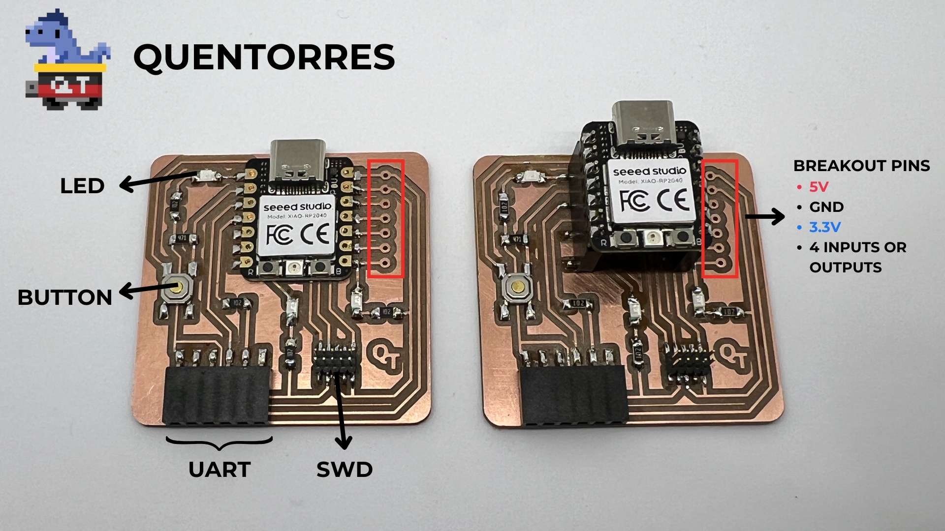
- Milling, soldering and programming the Quentorres. swd+uart adapter+hello board - xiao rp2040
- Creating a flexible circuit with the vinyl cutter
Group Assignments
The group assignment link can be found here
In the group assignment, we tested our milling machine with a v bit(milling cutter) for engraving and 1/100 inches flat end mill for drills and outline cuts.
-
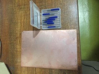
So what i've learned with this week group assignment is the ability to differentiate between material qualities of copper boards, some harve harder copper layers which makes them a bit heavier in weight and the other type which is the best quality are lighter in weight and the copper surfaces is smoother than the other quality pus the thickness is small too.
-
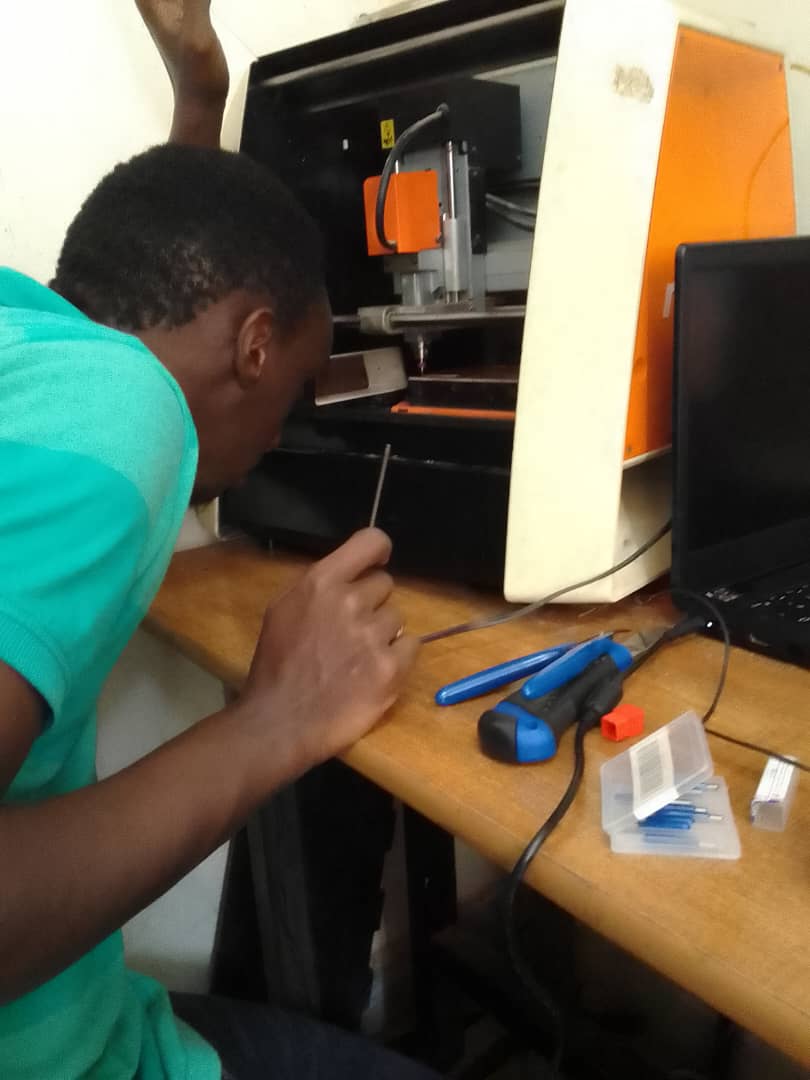
For tools i firstly learned that they are different are sharp compared to other CNC's tools and that they are easily broken so befure usage you need to check if the tip is not broken or chipped off to have a better result printing. Another thing is how to set up the machine to print the pcb, while setting axis one of the tricks that are helpful are to lower the tool after enclosing it into the spindle, before it touches the board then you loosen the spindle tool holder and let it fall on, this is done so that while moving the spindle to set the z axis we may not accidentally hit the material and damage the tool and also it's done in order to have a good printing outcome .
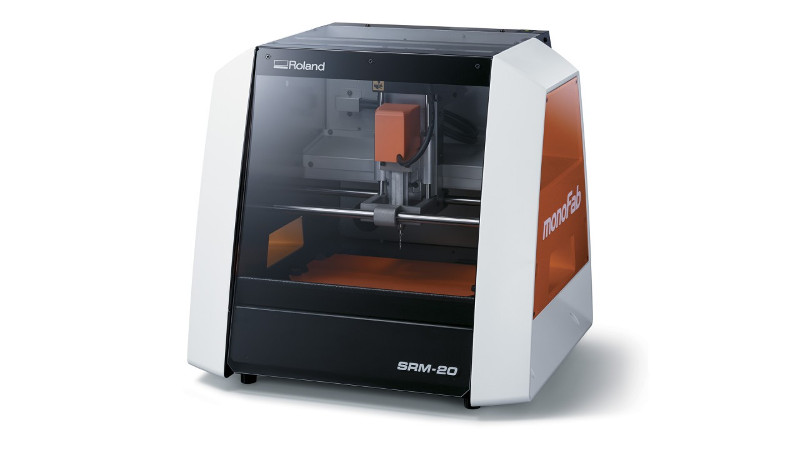
Our machine is a PCB Milling SRM 20 Machine from Roland, with a build plate of 232.2(X) x 156.6 (Y) mm(9.14 inches x 6.17 inches).
PCB Milling
I started with the provided design for the Quentorres. swd+uart adapter+hello board - xiao rp2040:
First i started with engraving, for this job, I used a 0.4 mm v bit(milling cutter) for engraving:

below are the picture that we had to load in the fab mods website so that we can generate the files for the pcb milling machine, we had three pictures to help make the pcb.
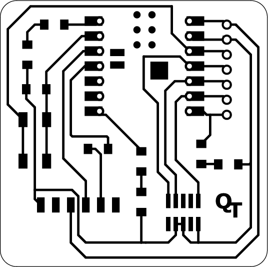
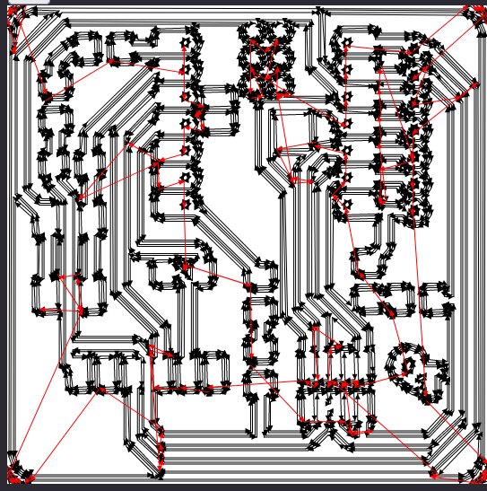
Below are the picture for cutting out the PCB and on this one i used same endmill i used drilling the circuit on the board after generating its files from fab mods.


Below are the picture for drills and on this one i used an endmill tool to drill the circuit on the board after generating its files from fab mods same as for outline.


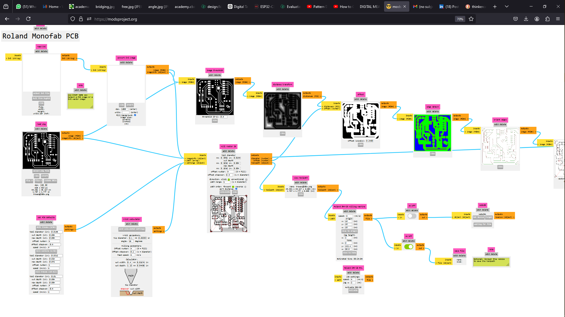
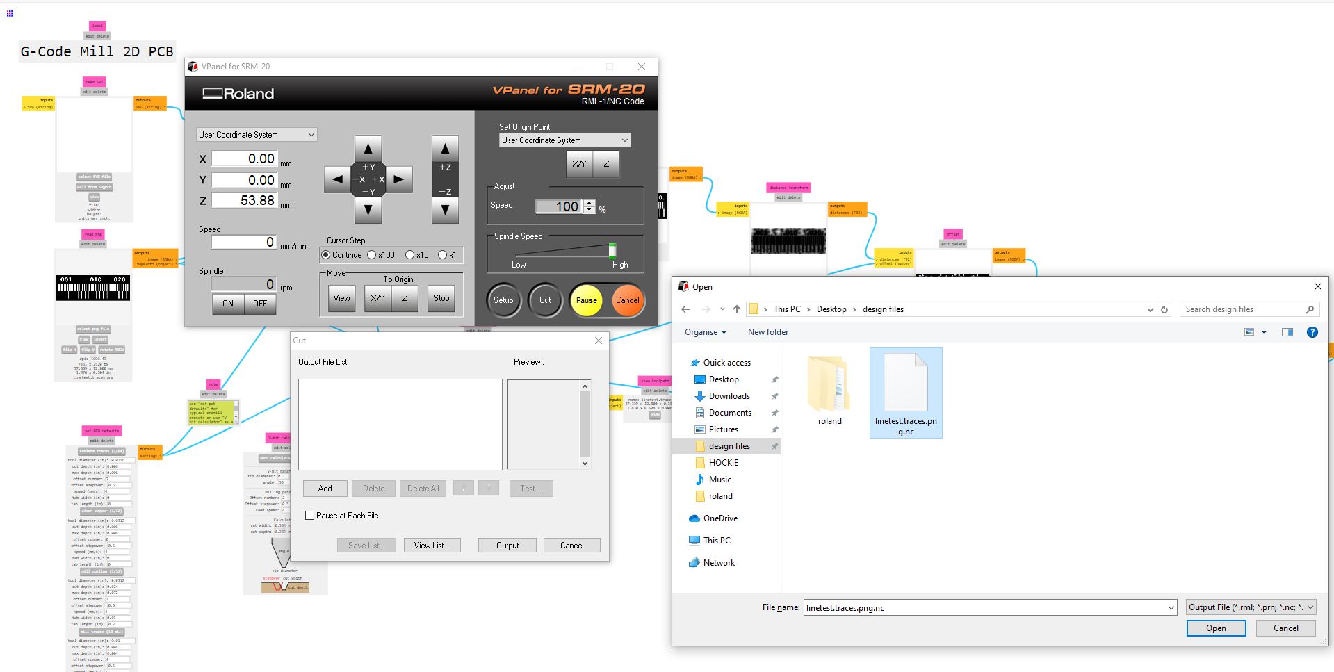
For the conversion to G-code, I followed the same procedure that was described in our class on electronics production. Namely, I used the program - open program - selected the machine which is the SRM 20 Roland - mill 2D PCB program in mods. I opened where i had to load the picture for traces, and the mill raster cell was set to:
- tool diameter: 0.3962 mm
- cut depth and max depth: 0.1016 mm
- Offset number: 2.5
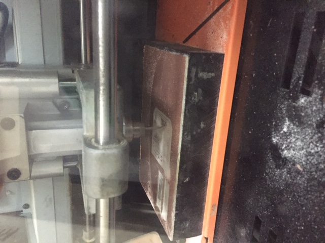
Set-up Milling machine and Milling PCB
In FabLab Rwanda we have SRM-20 monofab milling machine
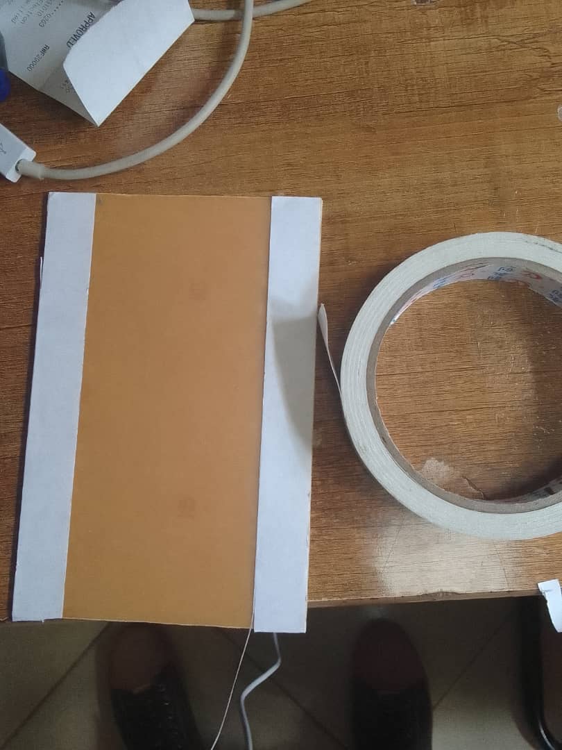
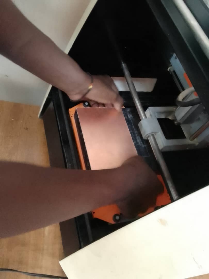
So for setting up the machine, i had the copper as the material to produce my pcb, a double sided tape to hold it on the bed of the machine and my v bits and Endmill tools to cutout the pcb. I proceeded with putting double sided tape on the copper material and laying it on the bed and then putting the tool(v bit) in the collet of the machine.
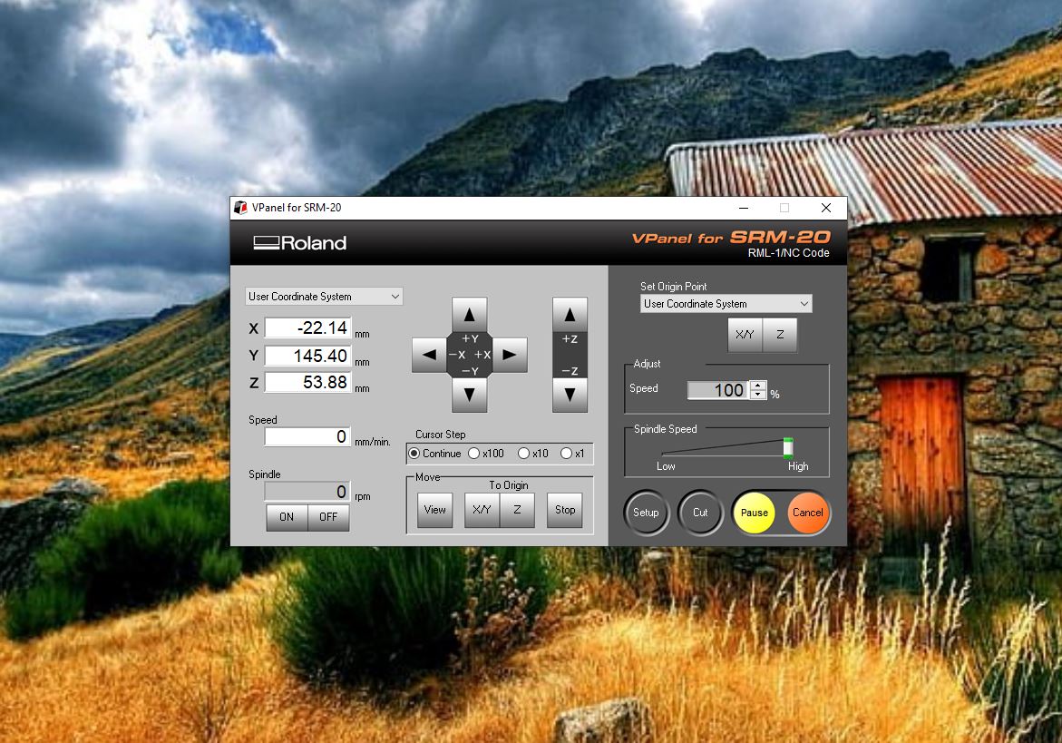
Setting up the controller of the machine
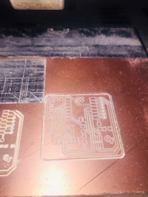
the machine has a controller, the Vpanel roland SRM-20 so we opened it to load the files generated by the modsprojects.org so we started by the testing files in order to identify and pick the the suitable traces size to use once we get to pcb design but also identify how efficient the vbit tool to be used can do traces. And so at first when you open it (first picture) the interface is simply contains coordinate system, tool movement buttons, curse step for moving fast or slow the axis, move to origin, set origin point, adjusting speed and other four buttons for set up (for machine configuration), cut(loading files), pause and cancel for stoping/cancelling the work. So when the software is opened the machine moves to the machine origin position, but its still has the origin of the last work to check this, click on XY button in the move section under TO ORIGIN and it goes to the origin of the last work done on the machine, you eliminate this by moving the axis to the point we want to be our work's origin and when we get there, go to Set Origin Point click on XY button to set xy origin point of our work, For the Z axis, after putting the tool in the collet i used the method explained in class to set the Z axis which is done by lowering the tool with the machine so that it gets nearer the pcb surface and then loosen it up by opening the collet and the tool fall on the surfaces, retighten the collet to hold the tool to that point click the Z button under Set Origin Point and then raise it up a little bit before it starts milling. To load files you click on cut it opens a window and click on deleteall to remove previous work, then click on add should directly take to the generated files, open them and then click on outpout and the machine starts right away.
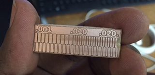
As you can see we came up with some good result but due to how small the traces are and the path of the tool the pcb got chipped on its right side as we were trying to remove the pcb from the board.
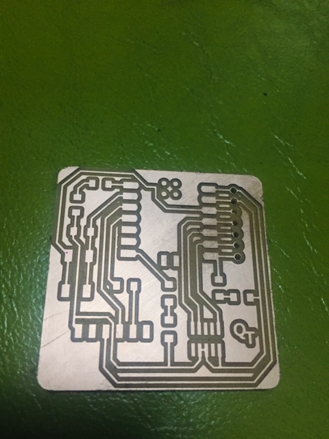
After seeing the test result i moved on to create the first quentorres pcb using the same process described above only by changing the work origin point.
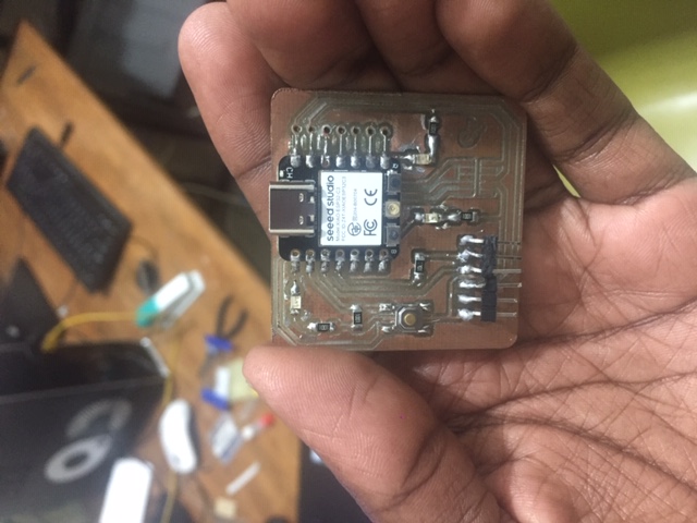
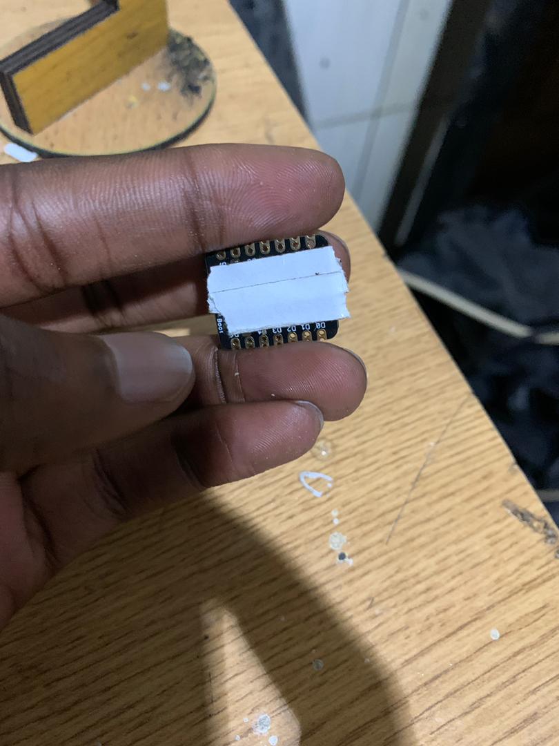
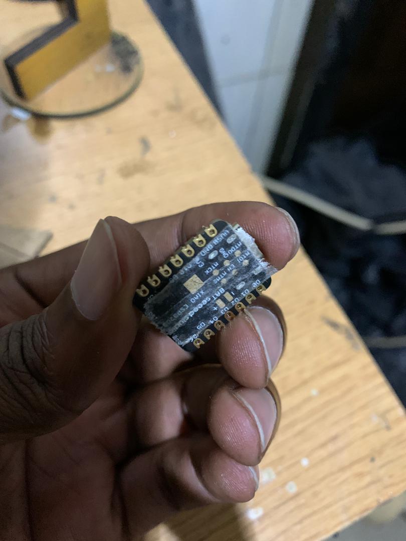
Concerns of a short circuit
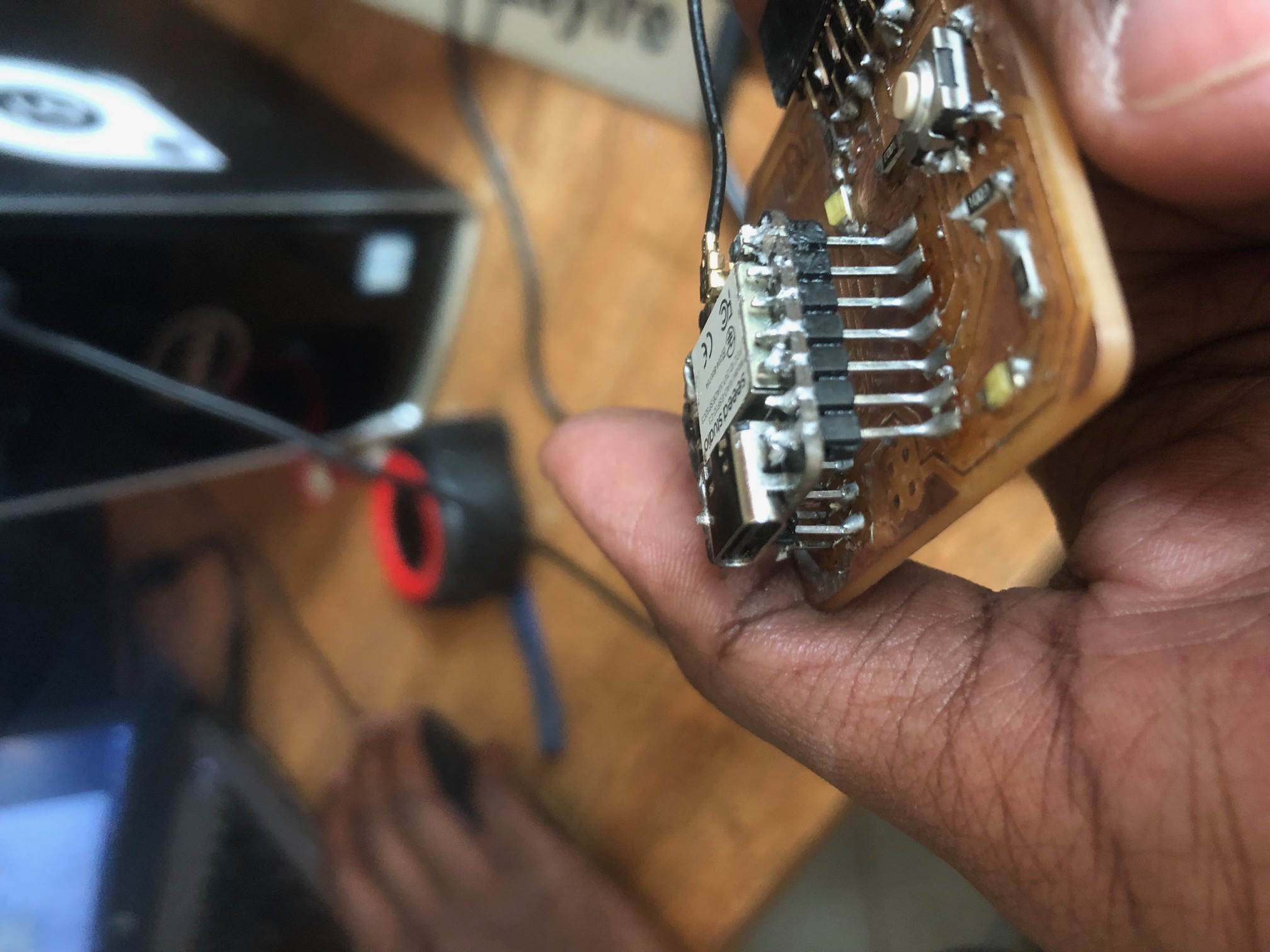
So as a notice, Due to the XIAO ESP32-C3 bottom of the XIAOESP32C3 having the pins for JTAG Pads, Battery connnector, Thermal Pads so to avoid the short circuit that could happen, you can use double sided tape behind your Xiao to prevent short circuits. Another method will be to solder the XIAO pins higher/in the air to avoid these pins on the back to touch the copper plate.
Programming
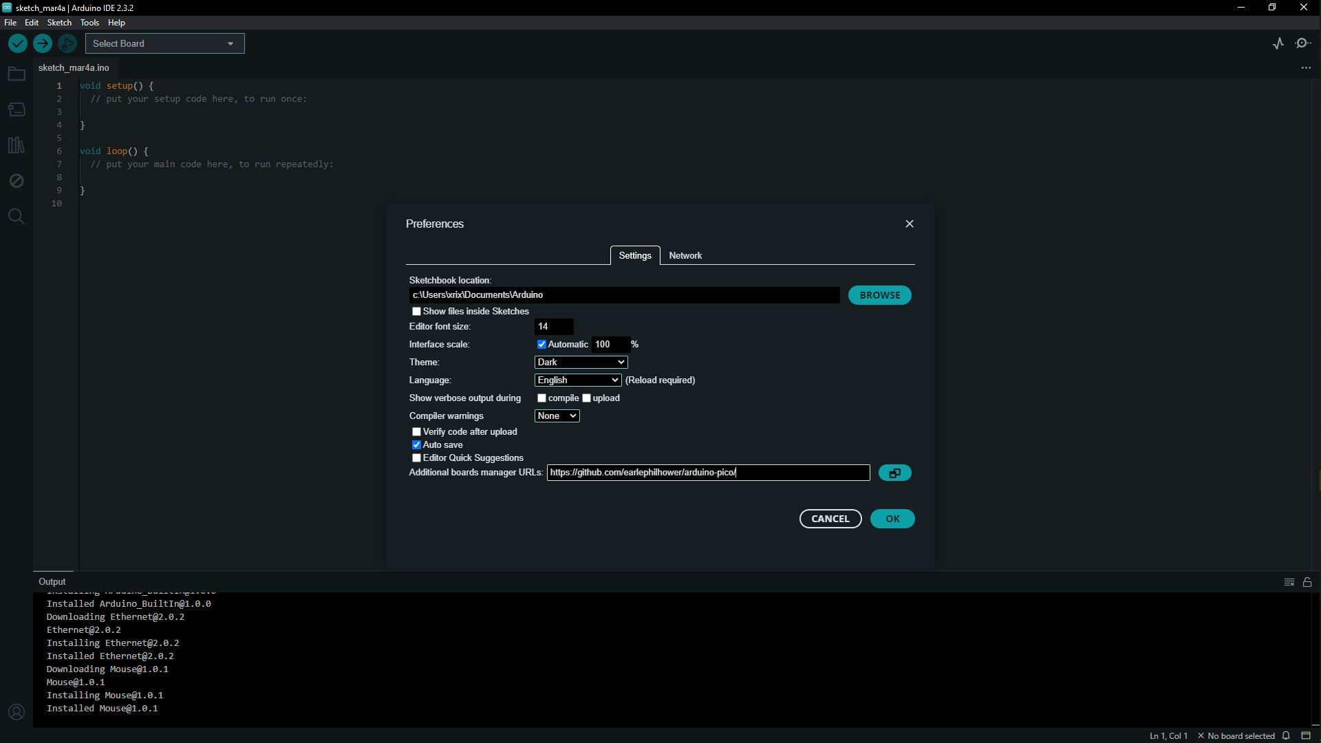
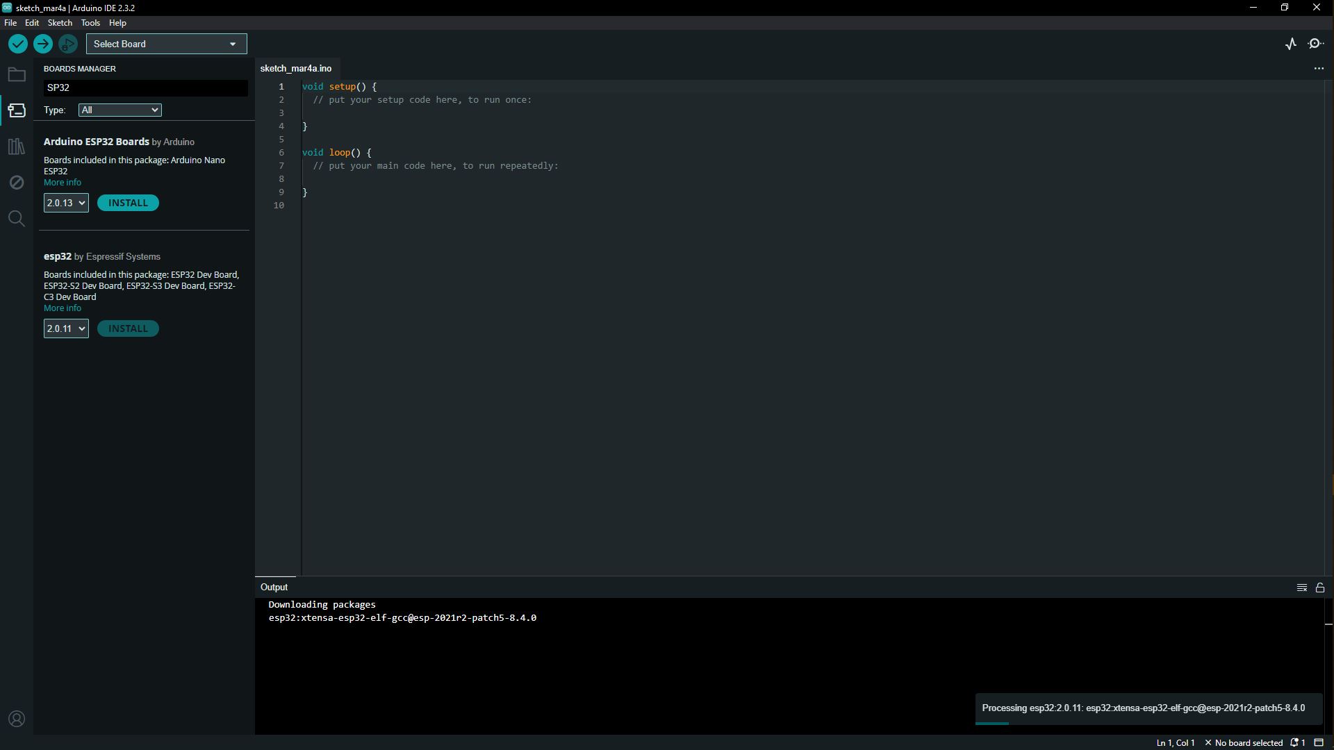
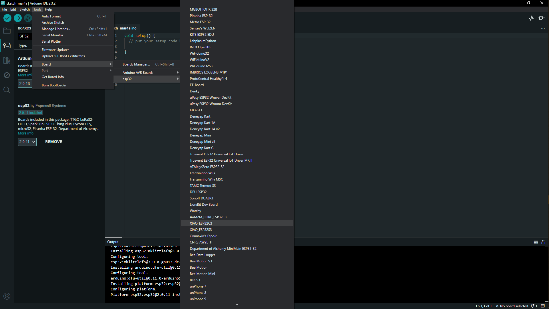
On this part i had to blink test the microcontroller development board which is this case is the hello board, so i had it already installed on my computer but for resources and the reason why i choose it is for it being an opensource software that makes it easy to write code and upload it to the board, so i opened it and the first thing i did was to donwload the additional boards by going to File->Preferences, we will add the URL of the additional boards that can be found here but i ended up not finding the XIAOESP32C3 board, so i went to the left corner column to the boards manager, typed esp32 then installed the esp32 by espressif systems after installation, i moved to configure my board, the XIAOESP32C3 by clicking to tools in the tool bar, then selected boards, then i selected esp32 then clicked on the XIAOESP32C3 to configure it.
Connecting the hello board successfully i had to activate first the port on which it was installed on by clicking on Tools in the toolbar, then scroll to ports, then depending on what port it is installed on, (you can check by going to windows and the device manager and check under ports) then activate the ports on which it's connected to, so after connecting and running, so in the arduino we have three main parts:
- the comments section where we declare what we call variables. Variables represent locations in the Arduino’s static RAM memory that are reserved for the data the variable is storing. I declared/created a variable, gave them a descriptive name LED1,2,3 and set it equal to the xiao ESP32C3 board pin they are connected on; to remind me of their purpose later on.
- Its start with curly { } - opening bracket & close with closing brackets. The void setup function executes only one time as soon as you upload, power up, or reset Arduino. In void setup, there are three things you have to know about, Serial.begin()a built-in function that passes one argument such as Serial.begin(9600), Serial.begin(115200) and pinMode () in void setup functions define how the pins of Arduino are to work either input or output. for my circuit i used the pinMode to turn on the LEDS on the hello board
- The void loop function takes no argument inside it. Code within Void loops functions repeat consecutively until Arduino is turned off. Whatever we write inside these curly brasses will run again and again. Its start with curly { } opening bracket & close with closing brackets. Whatever will be inside this will run from the top of the first line just after opening the bracket and end before closing the brackets. So i wanted the LEDS to light on from the first to the third and then light off again from the first to the third one after another differing in one second
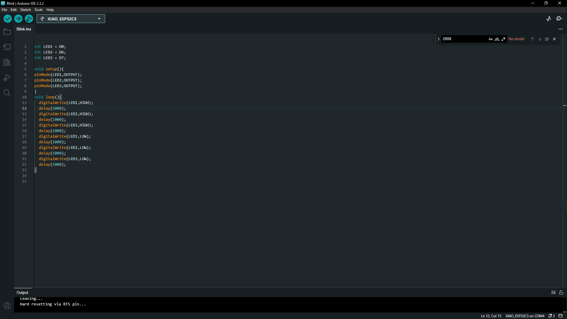
The block of codes that were are down below.
  int LED = D0;
  int LED = D6;
  int LED = D7;

  void set up(){

  pinMode(LED1,OUTPUT);
  pinMode(LED2,OUTPUT);
  pinMode(LED3,OUTPUT);

}
  void loop(){

  digitalWrite(LED1,HIGH);
  delay(1000);
  digitalWrite(LED1,HIGH);
  delay(1000);
  digitalWrite(LED1,HIGH);
  delay(1000);
  digitalWrite(LED1,LOW);
  delay(1000);
  digitalWrite(LED1,LOW);
  delay(1000);
  digitalWrite(LED1,LOW);
  delay(1000);
}
Short Hero video
Assignment Files